Introduction.
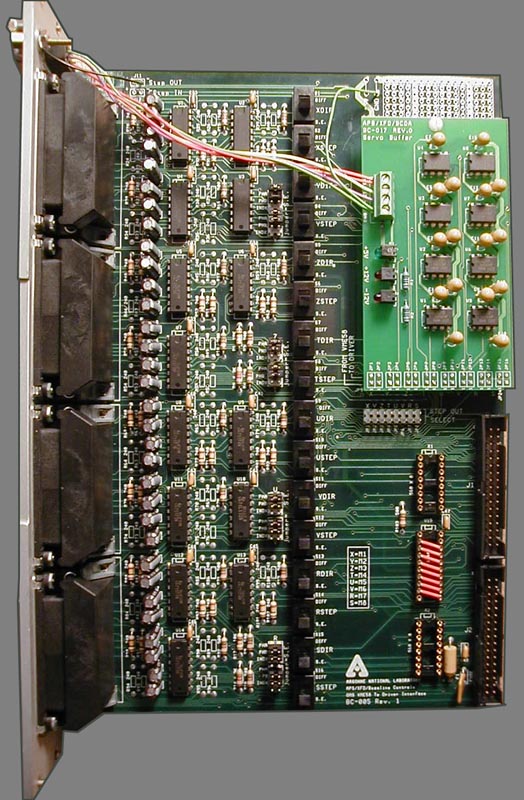
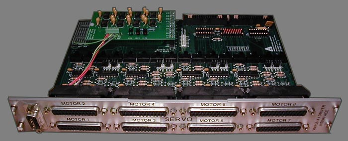
On 7ID in early 1999, we started using small MicroMo motors controlled by an OMS
VME58-8s servo card supported by the motor record in EPICS. The APS Beamline
Controls and Data Acquisition group designed a modified motor transition module
for the task. The links below describe the EPICS set up currently used on 7ID
to drive three slit units with small MicroMo servo motors. Similar installations
exist also at PNC and IMM-CAT. The work at Sector 7 was done by Ernest
Williams, Harold Gibson, Debra Hilborn, Tim Nurushev, Steve Dierker, Eric
Dufresne, Ron Sluiter (APS), Kurt Geotze (APS).
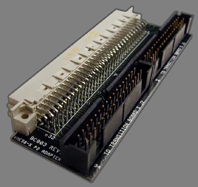
09/29/05 Please make sure that you use the correct version of the BC-003
paddle board. Only BC-003 rev. 2 will work with servo motors. Thanks
to Julie Cross for pointing this out.
See BC-003 harware manual on BCDA site.
EPICS record startup, magic tricks, bugs from 7ID experience.
To set up one motor:
1-Make sure the transition module is powered. The red and green lights on the
  module should be on.
2-Connect the motor to the transition module cable.
3-Refresh the motor record by typing the ENTER key in the P,I,D Coefficient
4-Enable the motor power
5-Tweak the motor and make sure the encoder are updating during the tweak.
6-If not, restart at point 3.
7-Make sure thet motor is not oscillating if so disable the motor and restart
  at point 3 until the motor stops oscillating.

Note when the VME crate reboot, it is possible that if the autosettings.req
file are not setup right, the motor will return in a disabled mode.
It is important then to enable the motor power again. Please make sure to
include all the PID (PCOF,ICOF,DCOF) fields and motor enable buttons in the
autosettings.req file.

The main bug is oscillating motors the first time it is set up. It is typically
easy to fix. This often occurs if the transition module power supply was turned
off with the VME power cycled.

Note that the OMS servo board are more sensitive to damage than the stepper
versions. We've damaged a few channels typically due to improper wiring, i.e.
putting 12 V on the encoder channels so care is needed.

We never tuned our parameters so I don't have much experience with tuning the
OMS servo loop. Defaults parameters worked for the Micromo motors mentioned
above and displayed on the screen.
